
The plunger coupler is the core part of the plunger fuel injection pump, and the plunger is one of the two precision parts that make up the plunger coupler. The chute is a common structure on the plunger (see Figure 1) and is the fundamental structure for adjusting the fuel quantity of the fuel injection pump and needs to be well controlled. To this end, the author designed a simple auxiliary measuring device that can be used to measure the data by clamping the workpiece.
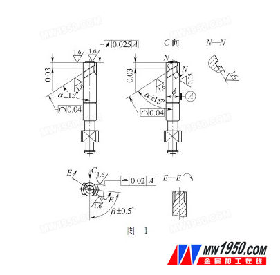
1. Analysis of the inclination angle α of the chute and the length H of the gauge
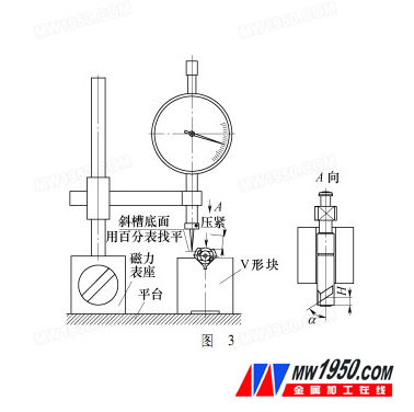
The structure of the JX-1 small tool microscope is shown in Figure 2. When measuring the inclination angle α of the plunger chute and the length H of the gauge, the bottom surface of the groove of the chute should be horizontal. The attachment of the JX-1 small tool microscope itself is the tip of the cathode and the sun, and the top of the plunger is between the tip of the cathode and the sun. Without positioning, it is impossible to maintain the level of the bottom surface of the plunger chute and thus cannot be measured.

Considering that the V-shaped groove is a commonly used positioning structure, if the plunger is lightly clamped on the V-shaped groove, the bottom surface of the inclined groove is leveled with a dial gauge on the platform, and then the plunger is clamped, and the plunger is placed. On the working table of the instrument, a thin needle is attached with Vaseline at the angle between the side of the chute and the bottom surface, and the angle between the plunger axis and the slender pin side busbar is observed by operating the table, which is α. Observe that the distance between the intersection of the chute contour and the plunger axis to the end face of the plunger is H. This measurement can be achieved. The initial structure is shown in Figure 3.
2. Analysis of the normal facing angle of the bottom surface of the chute
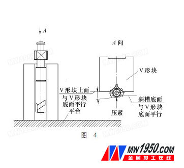
The normal plane of the bottom surface of the chute is a theoretical plane perpendicular to the bottom surface of the chute, and the angle between it and the flat position is actually converted to the angle between the bottom surface of the chute and the flat position. The angle between the planes formed by the two is only possible when the plunger is erected on the instrument table. However, when the plunger is erected, only the ridgeline of the flat plane can be observed. The ridgeline of the bottom of the chute cannot be seen, and the distance between the two parts of the plunger exceeds the effective adjustment distance of the focal length. At this time, if there is a conversion plane which is parallel to the bottom surface of the inclined groove, the angle between the bottom surface of the inclined groove and the flat position can be obtained by measuring the angle between the conversion plane and the flat position.
When measuring α and H above, the bottom surface of the chute is leveled, and the bottom surface of the chute is parallel to the bottom surface of the V-shaped block. At this time, the V-shaped block is erected, and the angle between the ridge line and the flat position of the V-shaped block can be observed to obtain the oblique angle. The angle between the bottom of the groove and the flat position, the angle of the angle is β (see Figure 4).
3. Measuring device diagram
Based on the above analysis, the measurement device is determined as shown in FIG. 5.
The measurement method mainly converts the measurement reference by the V-shaped block structure, so the geometrical tolerance accuracy of the V-shaped block is required to be high.
4. Implementation of the measurement

Measurements can be made using the above-described structural device, supplemented by a measuring platform and a magnetic stand. In order to eliminate the accuracy of the instrument and the comprehensive error of the device, a comparative measurement method is adopted. That is, the sample is measured and produced on the Wangong display, and then the sample is measured on the device to obtain a comprehensive error value. After the measured value, the corresponding integrated error value is added as the final measured value. Through comparison, the difference between the measured value and the measured value of the method is less than or equal to 4', and the length difference is ≤0.01mm.
5 Conclusion
The device has the advantages of simple structure, easy processing and convenient operation. It has been used for 5 years and meets the measurement requirements of the production site.
Armor Plate,Body Armor Plate,Plate Bulletproof,Body Armor Plate
Bulletproof Vest,Bulletproof Shield,Co., Ltd. , http://www.bulletproof-equipment.com