
1. Background and structure
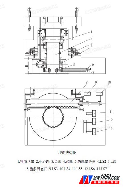
According to the driving method, the tool holder is divided into three modes: hydraulic drive under electric control, motor drive, electric motor and hydraulic drive. This article discusses the hydraulically driven ultra-precision square tool holder under electrical control. Taking the Taiwan Rising Hydraulic Square Tool Holder HP350 as an example, the structure is shown in the drawing. The tool holder is a hydraulically driven, electrically controlled ultra-precision automatic tool holder. The positioning of the tool holder is automatically performed by an internal proximity switch, and its operation is driven by hydraulic pressure. According to the instruction of the numerical device, it can be positioned in any four positions. According to its automatic centripetality, the precision can be guaranteed to 0.001mm. With the bite rigidity of the automatic locking device between the tooth and the tooth, the heavy cutting can be processed within 20s. Complete the tool change.
2. Failure analysis and processing
We found in the daily maintenance that the hydraulic square cutter holder will appear after the tool change command is issued, the tool holder does not move or the tool holder is raised without changing the tool position; the tool is not accurate or the pressure is not tight after the tool change. For such problems, in the maintenance, first remove the hydraulic failure. If it is a hydraulic failure, it is the same as other hydraulic stations, as long as it is properly processed to meet the pressure requirements. The following is mainly to discuss the failure caused by other reasons.
(1) The tool change command is issued and the tool holder cannot be operated. First check the electronic control proximity switch detection light is on, according to the function of each proximity switch, the detection light is red to indicate the correct position, and the gap of the switch for adjusting the stop block is 0.5mm. There are 7 proximity switches in the square tool holder, among which LS1 and LS2 are for detecting the lifting and loosening of the tool holder; LS3 and LS4 are for detecting the left and right end positions of the piston rack; LS5, LS6 and LS7 are for detecting the position of the tool change. Light up according to the order of each switch, if it is damaged, it should be replaced. If everything is normal, check if the reversing solenoid valves 1 and 2 are correct.
(2) The tool holder is raised without changing the knife. The tool change command is issued, the proximity switches LS5 and LS6 detect the tool position, the solenoid valve is commanded, the hydraulic cylinder with the rack supplies oil, and the rack drives the gear turret to rotate the tool change. If it does not work, first check if the solenoid valve is working. If it does not work, check if there is any leakage in the hydraulic cylinder. If there is leakage, the seal may be damaged, then the seal should be replaced; if the rack moves and the turret does not move, then It may be that the gear coupling or end cap is detached and needs to be replaced or reassembled.
(3) The tool change position is incorrect. Check if the position of the tool position switches LS5 and LS6 is accurate or loose. If yes, re-adjust the switch position or replace the damaged switch; if not, check if the gear coupling connection is in place or loose, otherwise, you need to It is reinstalled in place.
(4) Stop during the turning process. Adjust the bumper screw, not too tight, so that the hydraulic pressure can pass, and the turret can smoothly rotate to the specified position. It should be noted that after adjusting the buffer screw, the tool holder should be idling 2 or 3 times, and then locked.
(5) After the tool holder is lowered, the stopper cannot be retracted (the feed hydraulic cylinder cannot be retracted, and the detection lamp of the proximity switch LS2 is not lit). Loosen the nut of the LS2 and adjust the distance and position between the proximity switch and the stop block. The gap is around 0.5mm to see if the detection light is on. If the detection light is off, the proximity switch is damaged and the switch needs to be replaced. If it does not illuminate after the switch is turned on, it is necessary to consider the solenoid valve or wiring problem.
(6) The tool holder is out of control, and the rotation is multi-turn and cannot be stopped. When the site inspection is carried out, it is found that the equipment is running, and the failure phenomenon sometimes does not exist. And in the manual state, the turret often runs continuously for many steps without stopping, whether it is forward or reverse. And as time increases, the failure rate increases. According to the alarm number and alarm prompt, it can be determined that the tool holder motion system is faulty. After careful observation, it is found that the normal operation of the tool holder is as follows: receiving the index signal, the turret tool holder is lifted, and the tool position is rotated (still in the raised state), and the turret tool holder is reset down (ready to execute) An indexing action). The operation process under the fault phenomenon is that the turret tool holder is lifted and turned over one tool position without receiving the index signal.
According to the analysis of the fault phenomenon, the reception of the turret tool post indexing signal is normal regardless of the occurrence of the fault, and is independent of the rotation direction of the turret. Then it will be the transmission control of the rotation direction of the turret and the transmission failure of the indexing signal, focusing on several components related to the indexing action. Using the traditional method, that is, observing the signals of the various parts in the PLC to determine the fault location, since the fault is sometimes absent, it provides us with signals in both normal and abnormal situations. By comparing the signal difference between the turret lifting and the turret rotation action, it is found that both the turret tool holder locking reset sensor LS2 and the solenoid valve are in an abnormal condition. The solenoid valve is an output actuator whose action is controlled by the state of the input component. Therefore, the key to the problem is to further confirm whether the working state of the lock reset sensor LS2 is normal. First, the turret tool holder is jogged in the manual state, and the LED display at the root of the sensor is observed to judge that the locking sensor LS2 is abnormal. Remove the inspection and verify that it is damaged. Due to the damage, the solenoid valve can not be discharged for a long time, and eventually the turret tool holder cannot be reset. Troubleshoot after replacing the lock sensor.
(7) The turret tool holder rotates slowly, and the tool is not in place. When the pressure oil enters a cavity of the hydraulic cylinder, the piston rack drives the gear to rotate, and the turret rotates to change the tool. This action has control time, if time If it appears fast or slow, the tool will not be in place and the next action will not be possible.
The turret rotation is realized by the pressure oil control hydraulic cylinder. According to the working principle of the thrust hydraulic cylinder, when the hydraulic cylinder is working normally, the piston speed is V=4Q/Ï€D2, and V is the piston moving speed (m/). Min); Q is the hydraulic flow rate (L/min); D is the hydraulic cylinder inner diameter (m).
The angular velocity of the gear output is ω=8Q/πD2d1
Where ω is the angular velocity (r/min) of the gear output shaft; Q is the hydraulic flow rate (L/min); D is the cylinder inner diameter (m); and d 1 is the gear index circle diameter (m).
It can be seen from the formula that the flow rate and the angular velocity of the hydraulic cylinder can only be the flow rate, and the flow rate during operation is also certain. Only when the internal leakage of the piston cylinder occurs, the flow rate is lost, thereby causing the angular velocity to decrease.
Through this analysis and research, the sealing device of the two pistons of the hydraulic cylinder was inspected and tested, and it was found that the cause of the internal leakage was the wear of the piston sealing device, that is, if the piston showed internal leakage, when the left hydraulic cylinder entered After the oil, the pressure oil will enter the right end hydraulic cylinder from the seal wear of the two pistons and flow back to the oil pipe. Similarly, when the right hydraulic cylinder enters the oil, the pressurized oil will enter the left end hydraulic cylinder from the seal wear of the two pistons and flow back to the oil pipe. If the sealing element is severely worn, the external seal of the hydraulic cylinder cannot withstand the internal pressure of the hydraulic oil, or the external seal of the hydraulic cylinder fails.
Trouble-shooting method: The original seal of the piston is sealed by a Y-shaped rubber ring and a special hard plastic seal ring, but the dimensions of the Y-ring and the seal ring are all foreign standards. Inconsistent with China's standard series, we can not find a suitable domestic sealing element to replace it. The method is: by searching for data and trial and error, the final successful sealing component is a Y-shaped sealing ring, and two reciprocating O-rings are used for sealing. At the same time, the piston structure at both ends of the hydraulic cylinder is redesigned and improved, and these sealing components are reasonably distributed on the improved piston. After field experiments, the same effect as the original seal is obvious. After the official use, the work has been normal.
snap hook design,High Quality snap hook design,snap hook design Details, Dongguan Changhong Bobbin Co., Ltd.
plastic spools model Co., Ltd. , http://www.wire-spool.com