The minimum outlet flow rate of the pump is set to be slightly greater than the sum of the total system leakage, which only solves the requirements for meeting the process oil supply. In fact, the set minimum pump outlet flow is not sufficient to take away the heat generated by the mechanical efficiency and volumetric efficiency of the pump. In order to solve this problem, two measures were taken: forced cooling of the oil supply to the pump casing using a low pressure. The forced flow rate is taken as half of the maximum flow rate of the constant pressure variable pump. Because this flow is too large, the shaft seal of the pump will be destroyed due to excessive oil return resistance of the cooling oil, and unnecessary flow consumption is also increased. A low-resistance suction line design is used. The specific method is that the maximum flow velocity of the oil suction pipe is controlled within 0.2 m/s, and the reducer joint and the rubber hose with approximate parabola are adopted at the suction port of the pump, so that the total resistance of the oil suction pipe is small, and the suction pipe is effectively controlled. The negative pressure of the road limits the separation of air in the oil. Because the free air in the oil will reduce the bulk modulus of the oil, affecting both the variable mechanism damping ratio and the natural frequency of the variable mechanism.
Since the oil source unit was put into production in October 1999, the coarse adjustment and fine adjustment can be carried out simultaneously, and the speed of each movement meets the process requirements; the working pressure point set by the hydraulic pump has not changed; the system oil temperature is not In the case of changing the original cooling conditions, it has not exceeded 55 °C; the annual average equivalent electric power is less than that of the original system.
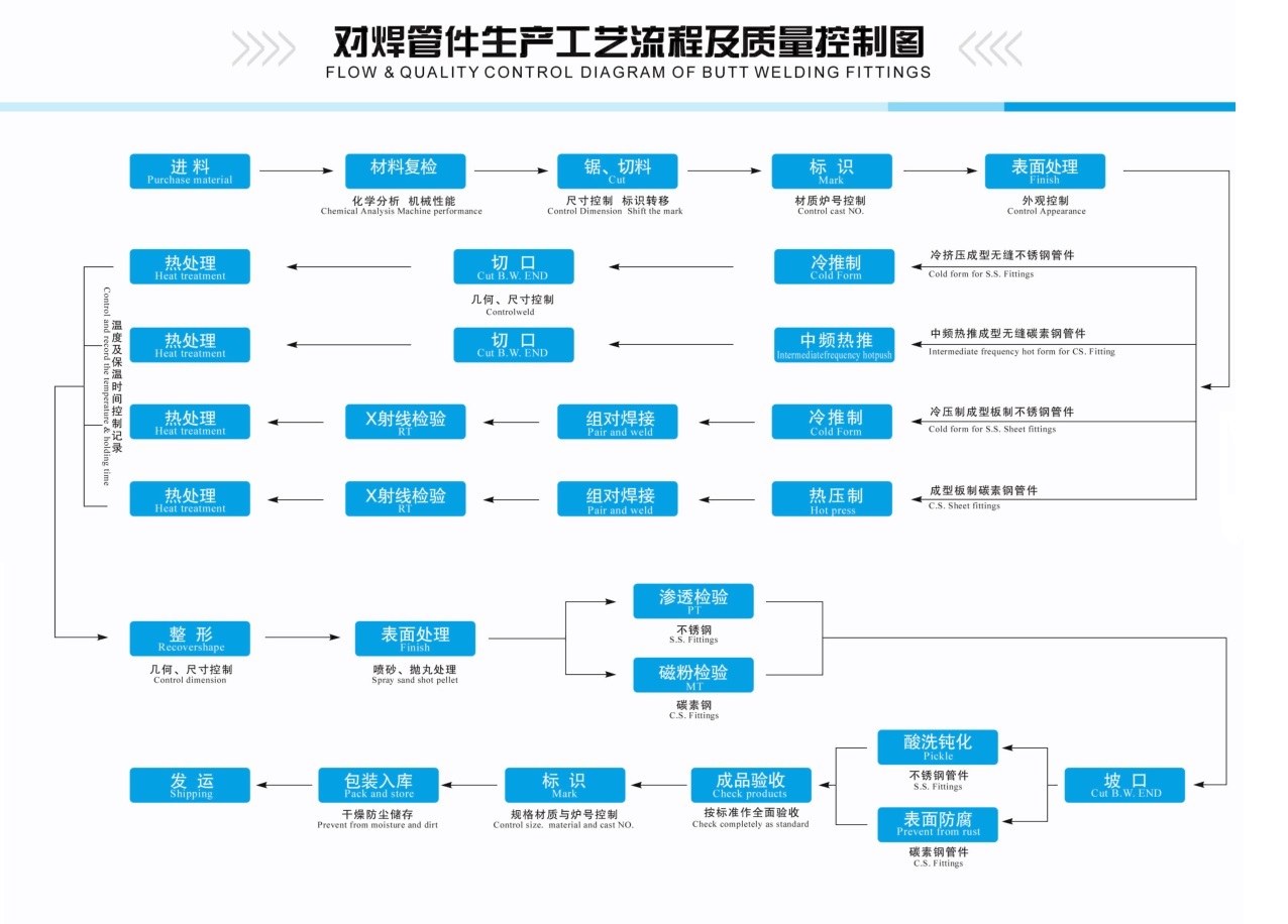
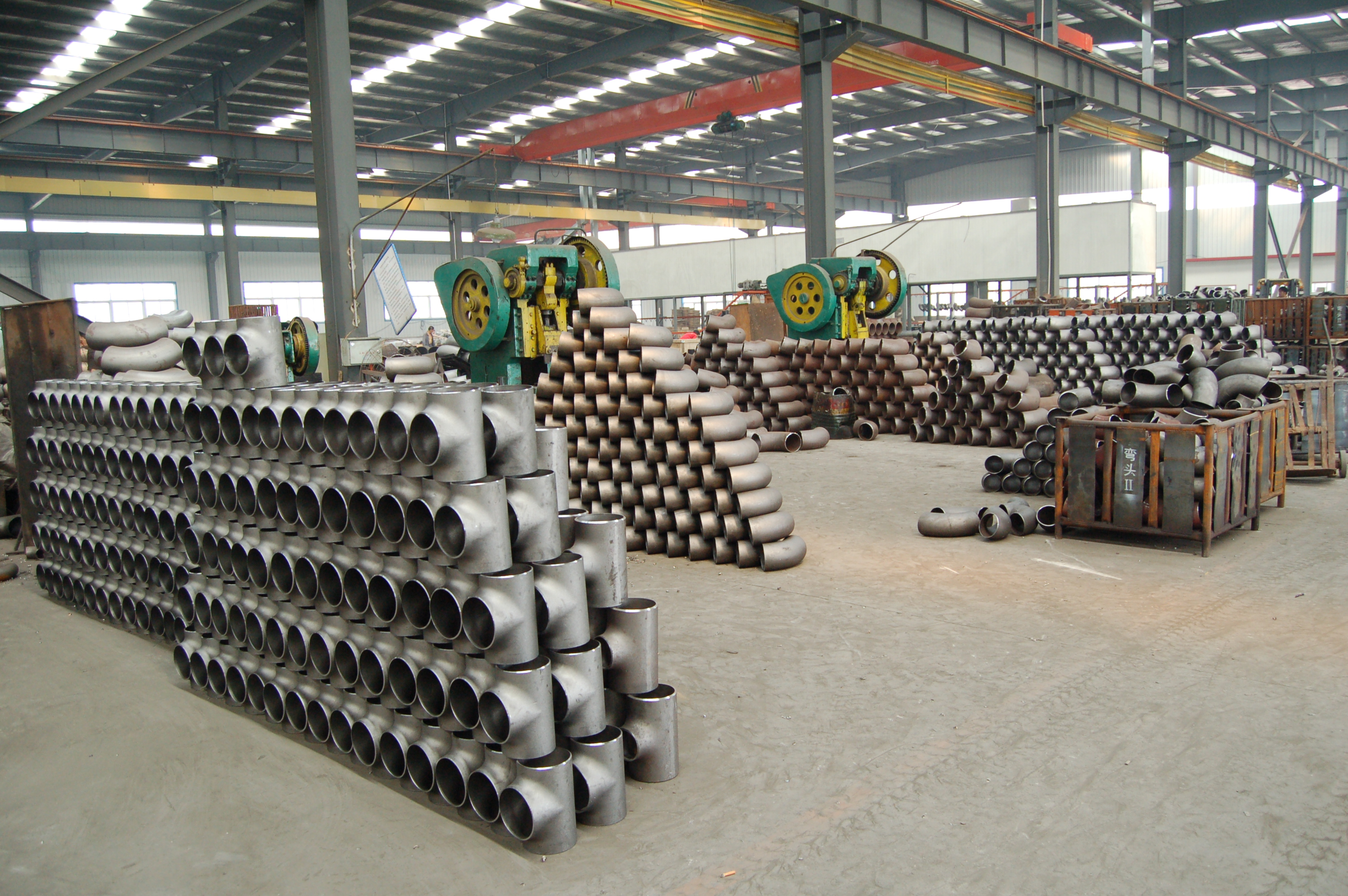
Butt-Welded Fittings including Elbows, Tees, Reducers, Caps,etc, manufactured strictly according to the standards such as EN,GB, SH, HG, JB, SY, ASME/ANSI, MSS, JIS, DIN and BS as well as the requirements of the customers' technical drawings. The butt-welded fittings are widely worked on the industries such as Petrochemical, natural gas,liquid gas, chemical industry, fertilizer', elechic power nucleal industry, shipbuilding, papenriaking, pharmaceuticals, food and health,building engineering and so on.


Butt-Welded Fittings,Pipe Fittings,Butt-Welded Elbows,Stainless Steel Pipe Fittings
HEBEI ZIFENG NEW ENERGY TECHNOLOGY CO.,LTD. , http://www.zifengpipeline.com
