introduction
NURBS has been widely used in the field of CAD. However, the application in the CAM field is relatively lagging. High-speed and ultra-high-speed machining are characterized by high efficiency, high precision, high flexibility and high quality. They are used not only in aluminum, cast iron and steel, but also in the processing of high-hard materials. It is regarded as a new direction in the field of modern processing technology. Compared with traditional CNC machining, high-speed machining has different requirements for machine tool spindles, tools, CNC systems, servo feed systems and CNC programming methods. The application of NURBS interpolation technology in the field of CNC machining is a supporting technology developed along with high-speed machining, which will greatly improve the overall level of CNC machining technology. Over time, its superior technical performance will be further developed.
Then the NURBS curve equation can be written
1 NURBS interpolation tool rail
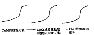
Figure 1 The first NURBS interpolation processing method
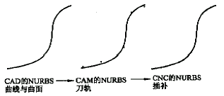
Figure 2 The second NURBS interpolation processing method
2. The geometric model defined by NURBS in CAD is converted into NURBS tool path by CAM system. The numerical control system performs NURBS interpolation operation by three types of parameters (control point, weight factor and node vector) in the tool path (see Figure 2). . This method does not have the method error of converting the linear tool path into the NURBS tool path, and the precision is higher, which is a more effective method.
| G06.2 | P_K_X_Y_Z_R_F_ K_X_Y_Z_R_ ... K_X_Y_Z_R_ K_ K_ K_ |
- In the high-speed machining of complex-shaped parts, the straight-line segment is used to approximate the shape of the part. In order to ensure the machining accuracy, the displacement defined by each NC code is small, so the NC code becomes very large, and the NC code of the three-dimensional part is generally longer than the NURBS tool path. 10 to 100 times. Due to the limited memory of the CNC system, it is often required to input the NC machining code into the CNC system in batches during the machining process. The DNC implements NC code transmission through serial communication. The transmission speed is generally between 110 and 38,400 baud, and the most common is 9,600 baud. If the average number of characters per NC code is 20 characters and the DNC transmission speed is 960 characters per second, only 48 NC codes can be transmitted per second. The actual transmission speed can only reach about half of the theoretical value. In this case, If the displacement defined by the NC code segment is 0.25mm, the machining feed rate that DNC ​​can satisfy is 360mm/min, which can not meet the requirements of high-speed machining, which affects the machining speed and makes the performance of the machine tool difficult to fully exert. One way to solve this problem is to use the NURBS tool path, and the second is to use the computer numerical control system network (DCN). The DCN transmission speed is about 1,000 times that of the DNC transmission speed.

Figure 3 Linear interpolation and NURBS interpolation feed rate changes
2. In linear interpolation processing, in order to reduce the speed impact of the linear end, the monitoring function of the CNC system to be processed (ie, the “feedforward†function) is continuously accelerated and decelerated at the straight end, and the NURBS interpolation tool rail is within the allowable machining direction. Internally, no acceleration or deceleration is required, which increases the machining speed (see Figure 3).
3. In the high-speed machining, the NC code block processing capability of the general CNC system often cannot keep up with the high-speed processing speed of the code segment; or the processing speed is reduced; or the high-speed sacrifice accuracy is maintained (increasing the length of the straight line segment to improve the code execution time); The displacement of a section of NURBS interpolation tool often includes the displacement of the linear tool path of 10 to 100 segments, which reduces the requirement for the NC code block processing capability of the CNC, and thus can often meet the requirements of high-speed machining. Table 1 compares the NURBS interpolation and linear interpolation processing of a part. It can be seen from the table that the NURBS interpolation is reduced by more than 30% compared with the linear interpolation processing time.
| Interpolation method | Standard mode | Quick mode | Finishing mode |
| NURBS | 102min 5s | 75min 37s | 111min 4s |
| Linear | 141min 56s | 124min 54s | 157min 38s |
4. NURBS interpolation avoids the use of straight lines, thus improving the machining accuracy of the workpiece and improving the surface quality. As shown in Table 2, taking the CNC system of the usual 1ms servo cycle as an example, even if the feed speed is 30m/min, the displacement in the unit servo period is only 0.5mm, that is, in the NURBS interpolation. Approximating with a linear displacement of 0.5 mm. If the linear tool path has a displacement increment of 0.5 mm, the code file becomes large and it is almost impossible to perform economical and reasonable processing.
| Servo cycle Ms | Incremental displacement at different feedrates during the servo cycle Mm | |||
| 2.5 | 10 | 18.8 | 30 | |
| 20 | 0.833 3 | 3.333 3 | 6.266 6 | 10.000 0 |
| 10 | 0.416 6 | 1.666 7 | 3.133 3 | 5.000 0 |
| 3 | 0.125 0 | 0.500 0 | 0.940 0 | 1.501 5 |
| 1 | 0.041 6 | 0.166 7 | 0.313 4 | 0.500 0 |
| 0.4 | 0.016 7 | 0.066 7 | 0.125 4 | 0.200 0 |
| 0.1 | 0.004 2 | 0.016 7 | 0.031 3 | 0.050 0 |
2 NURBS interpolation of computer numerical control system
| D d = | l 2 | = | v 2· t 2 |
| 8 r | 8 r |
3 Conclusion
Watch Case 18 Watches Collectors Aluminum Bri,Aluminum Watch Storage Box,Waterproof Camera Case
RUNVA ENTERPRISES LIMITED , http://www.toolboxcn.com