
Foreword
The connecting rod type stamping parts are widely used as a connecting piece in the electrical industry, and the dimensional accuracy is high. It plays a role in transmitting the connecting force. If the size does not meet the product design requirements, the entire transmission mechanism of the product will be Serious impacts may prevent the transmission from functioning properly. Secondly, the shape itself is more complicated, and the stamping of a plurality of different properties is one, so the formation is difficult.
There are two options for producing such parts: one is done in a simple multi-payment mold that is dispersed in a conventional process, and the other is that the process is concentrated in a mold-level progressive mold. The former requires a large number of equipment, molds and workers, the labor intensity of the workers is large, and because the mold is used to complete the entire production process of the parts, various factors will cause processing accumulation errors, especially for some high precision and large output. The quality and quantity of the connecting rod parts are difficult to guarantee in a single-process mold. When the shape of the workpiece is relatively complicated and the shape is small, the strength of the concave-convex mold of the single-process mold is restricted, and it is difficult to handle the positioning of the front-rear process, and the interference between the processes is formed before and after.
In this paper, the progressive die design of the parts shown in Figure 1 is emphasized, and the superiority of CAD design in the progressive die of the connecting rod parts is emphasized.
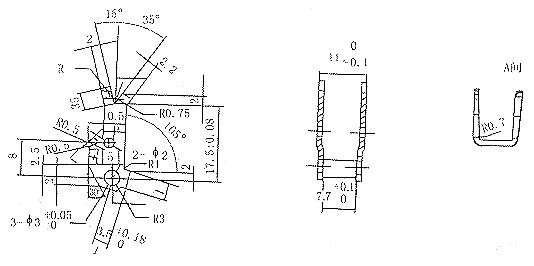
figure 1
1 part process analysis
The connecting rod parts shown in Fig. 1 are integrated into stamping processes of different properties such as punching, fixing, bending partial polishing, forming bending and the like. The illustration shows the layout of the part. From the point of view of the accuracy of the parts, 2-Φ3+0.05D has the symmetry requirement IT10 level, the link height dimension accuracy IT11 level, the forming bending opening dimension precision IT11 level, and other dimensional accuracy are IT16 level. It is a general punching, but the shape of the formed part is more complicated and the forming direction is different. Due to the large output of the parts, it is considered to adopt a progressive die structure, and from the design point of view, it can be produced on a high-speed punching machine, and the shoulder format guide plate is designed.
The main forming difficulty of the part is that the partial bending direction and the feeding direction have an angle of 15°. When designing the mold, considering the processing difficulty, the upper and lower sides adopt the inlaid structure at the same time, so the mold design and processing requirements are required. It is even higher. Therefore, the arrangement of the bending process is the key to the layout design, and it is also the key to realize the progressive stamping. According to the principle of decomposition of the multi-station progressive punching and bending process, firstly, the upper and lower movements of the mold are used to complete the excess waste of the shape of the part, and the partial repairing is considered before the bending is performed. After the above-mentioned punching and bending is completed, the strip is lifted up by the ejector device and is raised by a projection height of 2 mm for smooth feeding. Once the bending scheme is determined, other processes can be arranged to make a layout drawing.
1.1 Conventional manual design
1.1.1 Determination of each station and cavity
The bending of the parts is carried out by looking up the table to carry out the manual slab expansion, drawing the plane geometry, and decomposing according to the geometry at each station to determine the relative positional size and the geometrical dimensions of each decomposition pattern. The theoretical calculation of this working process is A rather complicated and cumbersome one, especially for random geometric figures, is more difficult. As long as there is a slight error (error) in the calculation of one station, then the design of each station pattern of the entire progressive die is large. influences.
1.1.2 Pressure Center Determination
In order to ensure the correct balance of the die, the punching force must coincide with the center of the machine tool slider through the axis of the die, which can improve the life of the die, reduce the wear of the die and the machine guide rail, and avoid stamping accidents.
For a single symmetrical graph, the pressure center is at the geometric center of its contour graph, and the complex head graph can be used to find the pressure center using analytical geometry.
formula:
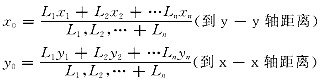
For a plurality of graphs, the pressure center is solved by the above formula, and the pressure center is obtained according to the multi-cavity, and the formula is the same as above.
1.2 Using CAD Design (UG Software)
1.2.1 Building a part into a shape
In the modeling, various modules and curves can be used to build the part solid model, and the feature model is applied and edited.
1.2.2 Parts rib expansion
The material thickness a is defined first to determine the elbow expression (expression) bndcl=(b+K*a)rad(c) into the Application for rib expansion, and the computer automatically expands the parts into a flat pattern.
1.2.3 Arrangement and combination of each station
The obtained planar graphics are copied multiple times according to the stamping step size, and the planar graphics are trimmed to obtain a reasonable layout pattern for each station stamping process.
1.2.4 Multi-cavity pressure center determination
Select all station closures, curves, and use the grip programming software (YLZX) to find the pressure center coordinates (X, Y) of all curves at once. This provides a good theoretical basis for the progressive die design and saves a lot of complicated theoretical calculations.
1.2.5 Establishment of layout graphics
According to the above design steps, the mold engineer can make a correct judgment based on his own and the factory's practical experience, and correct the design results. Speed ​​up the design process, which shortens the mold design cycle and improves the quality of the mold design.
According to the above operation comprehensive analysis, determine the layout diagram as shown in Figure 2, there are 8 stations, (1) punching, cutting, 4 holes for the part hole, the remaining 3 holes as the guiding hole of the post-process; 2) Cutting, making the bent part of the part and the strip partially separated, and designing the guiding nail at the station to guide the strip; (3) cutting, so that the bending part of the post process is completely separated from the strip, (4) Partially repairing the light, the polishing punch is small, and the light-fixing punch and the die are matched with each other when the light is being repaired, thereby increasing the strength of the polishing punch; (5) fixing and bending, The upper and lower molds are hard (restricted by the limit block on the stripper plate). The guide nail device of the station is on the fixed bending punch to eliminate the positioning error caused during the feeding process; (6) Forming and bending In order to prevent the rebound of the parts during the forming and bending process, the quality of the bent parts is ensured, and the pressing ribs are processed on the curved lower mold blocks while bending, and the parts are rebounded; (7) partial cutting and separation, taking into account the specific circumstances, The part can not be separated once, separated twice before and after; (8) Finally cut off the separation, at this time the part falls in the concave model cavity, the strip is forwarded, the part is sent Take out the concave model cavity and complete the stamping process.
The layout is shown in Figure 2.

figure 2
1.2.6 Mold parts assembly
After completing the design of the necessities of the mold parts, in order to verify the rationality of the structural dimensions, it is necessary to assemble the parts as a whole, and check whether the position and assembly dimensions of the parts are reasonable and whether there is interference. And to correct, to avoid mold processing and design problems in the manufacturing process.
1.2.7 Mold parts manufacturing and processing
In the model established by UG software, the CAD/CAM system is used to transform the two-dimensional product parts drawings into three-dimensional shapes on the workstation. Through the three-dimensional modeling, the various parts constituting the mold are designed, and the parts that need CNC machining are processed, and the NC program of the numerical control machine tool is directly compiled, and the shape of the part is processed and formed by the machine tool, and finally assembled into a qualified mold.
Working process of mold structure design points
The key to the design of the progressive die structure of the connecting part stamping parts is to solve the multi-angle and multi-directional bending of the connecting rod. To achieve this goal, the order of each process must be arranged.
2.1 Floating loading device
Connecting rod parts often have some convex depressions. In the design of the progressive die structure, if these parts are not handled properly, it may cause obstacles to the feeding process. The solution to this problem is to design a strip lifting device, which is often a floating top nail. When the stamping is completed, the random bed slider of the upper mold rises, and the top material nail mounted on the lower mold bounces under the action of the spring force below. The highest position of the top is the feeding plane of the strip, and the height of the jacking should be guaranteed. The material is not obstructed by the protrusion formed by bending or the like during the feeding process, and a limit step is arranged on the guide plate to prevent the strip from coming up with the punch and causing the mold to be damaged.
2.2 Structural design features
2.2.1 Part design
In the progressive die, the outer die dimensions, if the overall structure is used, in the mass production of the parts, if the mold is not properly operated and normal wear, this will bring difficulties to the repair process of the mold, so in the mold design process In the middle and the upper and lower molds, the inlaid structure is adopted in multiple places, and the position of the inlay is selected in the fixed bending position, which is beneficial to the processing of the hole and the stress distribution of the improved hole, thereby improving the life of the mold and facilitating the maintenance of the mold.
2.2.2 Mold structure
The four-column column is used to integrate the upper mold and the stripping plate to enhance the rigidity and guiding precision of the stripping plate. The stripping plate is additionally provided with a pressing plate. The stripping plate and the pressing plate are separated structures, which is easy to assemble the clamping plate and press plate. Cooperating with the punch to H7/h6, it has better guiding protection for small convex molds. A limiting block is arranged between the stripping plate and the upper fixed pole for easy calibration. The structure has begun to get more and more applications in our factory.
2.3 mold working process
When the punch slider rises, the floating material feeding mechanism lifts the strip under the action of the lower spring (higher than the plane edge size of the concave die is 3mm). When the punching mechanism feeds the material to the position (the current factory has no The equipment is fed by hand. When the punch slide is lowered, the guide nail automatically guides the material, the stripper presses the strip, and the upper punch completes its work. The reset of all mechanisms relies on the respective return springs.
Figure 3 is a schematic diagram of the overall structure of the progressive die (shown in the drawing)

image 3
Conclusion
For the design of such connecting rod parts and progressive molds, as long as the forming difficulties of such parts are grasped, and these parts are reasonably decomposed, and the forming mechanism which is favorable for local forming is correctly selected, the production requirements can be designed. Qualified product parts, through the actual production in the factory, fully verified the superiority of CAD in the joint design of the link-level progressive die, and the rationality of the arrangement of each process is a successful, stable and reliable progressive die.
Butterfly Valve,Sanitary Butterfly Valve,Stainless Steel Butterfly Valve
Antai Magnet Co., Ltd. , http://www.buxiugangvalve.com