
The axle box is an important part of the locomotive bogie. Its main function is to make the drive motor mesh better with the gear on the axle to ensure smooth operation. At this stage, in the locomotive design, the part of the bogie is usually very compact, which makes the axle box destined into a thin-walled profile. The overall processing quality of the axle box will directly affect the driving safety of the locomotive.
   1. Processing status of the axle box
Taking the DF8B locomotive hug box (see Figure 1) as an example, most of the non-machined dimensions of the box are not more than 15mm; the bearing positions of the two ends are rounded, and the middle part is designed to be non-round, for the drive motor. The motor is mounted on the intermediate plane by bolts.
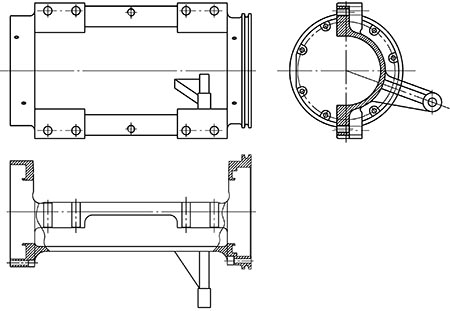
Figure 1 DF8B axle box outline drawing
Due to the complicated structure, the axle-carrying box material adopts the C-class cast steel with good toughness, and adopts the conventional machining method. The basic processing steps are: blank casting→cleaning→annealing→clearing→spraying→scoping→roughing→welding→ Semi-finishing → finishing → flaw detection → inspection.
   2. Processing difficulties analysis
In the RAM analysis of this product, the primary failure rate is the bearing hole size and shape tolerance at both ends. This factor will directly affect the bearing installation, and the overall impact on the axle's usability. If there is a problem, it will directly cause bearing failure and endanger the driving. Safety.
(1) Casting shaft box casting quality requirements: The material of the holding axle box is C-grade steel, and its control difficulty lies in the influence of casting quality and subsequent defect processing on the processing size and shape size.
(2) Main dimensions and shape tolerance requirements of the axle box: The hole diameters of the bearing holes at both ends are φ344+0.057 +0mm and φ360-0.041 -0.098mm, respectively. The bearing hole coaxiality at both ends is 0.04mm. The bearing hole is directly assembled with the bearing, and the cylindricity requirement is 0.015mm, and the dimensional tolerance is 0.057mm.
   3. Process improvement measures
In order to ensure the quality of the product and discover the casting defects in time, the ultrasonic flaw detection is added to the inside of the motor surface and the end faces of the two bearing holes after the roughing process to avoid major casting defects after semi-finishing. Through the multi-batch inspection, it was found that there were several obvious problems: due to the problem of the blank of the casting, although the repair welding was taken after the roughing, there were still many defects and cracks in the subsequent processing. Especially in the bearing holes at both ends, there are often large looseness in the finished hole, such as sand, sand and cracks. Because of the small amount of retention, it is more difficult for subsequent processing. Moreover, since the product belongs to a profiled thin-walled member and a semi-circular structure in the middle, there is no tempering condition after multiple repairs, and the welding stress and the processing stress cannot be eliminated in time, so that the hole deformation is large after the machining. Although the test is qualified at the time of processing, after the product is released from the tooling, the dimensional difference is large when the test is again performed, and the pattern requirement cannot be satisfied. In response to the above problems, analyze and take improvement measures one by one.
(1) Improve the casting process and reduce casting defects. As we all know, the closer to the riser, the more defects there are. In the existing casting process, the riser is near the bearing hole at both ends. The defect of this part is more common after processing, and it is not easy to handle. Therefore, the position of the riser in the bearing hole is changed to the riser on the motor surface. Moreover, the processing amount on the motor surface can be appropriately increased, leaving a margin for subsequent defect disposal, which can ensure multiple processing and tempering after rough machining.
(2) Adding processes before finishing to eliminate internal stress. The process of adding before finishing is flaw detection, welding repair, annealing and shot peening. The specific method is: in the rough processing of the blank, all the processing surfaces are formed into a shape, and the normal amount is 1mm. After roughing, all the processed and non-machined surfaces are inspected comprehensively; the non-machined surface is focused on visual inspection, and the materials and defects are marked out in time to avoid affecting the overall quality after subsequent processing; magnetic particle inspection on the machined surface Find all cracks, loose, obvious sand holes, sand inclusions, etc., and mark all the defects clearly; then treat all the processed and non-machined surface defects uniformly, and the treatment method is to use special welding rods for heat insulation welding, all defects and cracks All elimination; re-inspection after grinding; confirmation of high-temperature annealing without cracks, eliminating all processing and welding stress, avoiding the subsequent release of stress after subsequent processing, resulting in unstable product processing dimensions.
Through the process adjustment, the improvement effect obtained is: in the subsequent processing process, the processing performance after the secondary failure of the blank is greatly improved; due to the prevention and multiple treatment of the original defects of the casting, no welding occurs in the subsequent processing. Hard spots, sand inclusions, sand holes, etc., as well as abnormal wear and chipping of the tool, which affect the size and appearance quality of the product. At the same time, since the tempering is thorough, the dimensional change after processing is small. Through the tracking and inspection of 2 sets of 12 products, the processing size changes are all within 0.01mm, indicating that the process improvement basically solves the problems of deformation, lack of material, abnormal wear of the tool or chipping, which affects the quality of the product, and is effective and effective.
   4. Subsequent improvements
In the subsequent fine boring process, the workpiece should be inspected before the workpiece is not released after the machining. If the size is not in place, the tool correction should be performed in time to perform interpolation. However, there are several times when the test is released before the workpiece is released, and the dimensional ellipticity is guaranteed to be within 0.01 mm. However, once the clamp is released and tested, it is found that there is a big difference between before and after, and sometimes even the size is out of tolerance. The phenomenon.
In the early stage, the treatment plan for blanks and defects has been verified to be more effective and feasible. For the problems in the fine boring, the reason can only be found in the machining method. Several processes during roughing have no effect on the follow-up. For example, the surface of the rough-milling motor, the bolt holes, etc. are all machined in front of the finished bearing hole, and the motor surface and bolt hole are also used when finishing the bearing hole. As for positioning and pressing the workpiece, as shown in Figure 2.
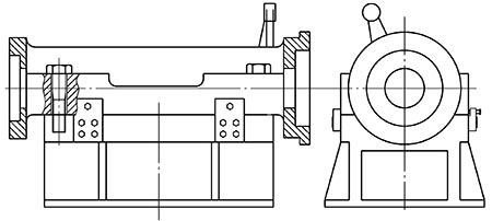
Figure 2 rough machining diagram
It can be seen from Fig. 2 that the motor surface and the tooling face each other, and the axle box must be pressed tightly before machining, and the screw hole on the reverse side of the axle box is also used for pressing. Because the bonding surface is relatively long, the analysis may be subject to the following reasons: 1 because each worker has a different habit, and the pressing force is different. When the two bolts are tightened, the order of the four bolts is inconsistent, and the stress on each part is uneven, which tends to cause large deformation after processing.
The improvement scheme is as follows: the contact area between the tool and the workpiece is reduced, and only the amount of the four bolts is pressed, so that the pressing portion has sufficient support; the tooling is modified, that is, the axle box and the tooling are only retained in the bolt pressing portion. Contact, the rest of the processing removed 0.5 ~ 1.0mm. After the improvement, after multiple inspections, the design requirements are fully met.
   5 Conclusion
Through the actual processing verification, by reducing the blank casting defects, eliminating the internal stress and improving the processing methods and other technological measures, the problems encountered in the machining process of the locomotive axle box are basically solved, and the solution is more effective and feasible. The processing provides a new process idea.
references:
[1] Deng Xiaojun. Analysis of the rolling axle box of traction motor of Dongfeng 5 locomotive[J]. Diesel Locomotive,2002(11):3,11-13,23.
[2] Wang Jingmei. Optimization of heat treatment deformation process for thin-walled parts [D]. Changchun: Changchun University of Science and Technology, 2012.
[3] Wang Feifei. Method and Application of Local Heat Treatment of Thin-walled Parts[J]. Thermal Processing Technology, 2014(8): 189-191.
[4] Zhou Gang. Discussion on Welding and Repairing of Rolling Bearing Box for DF4D Locomotive[J]. Diesel Locomotive, 2012(7): 35-37.
[5] JB/T 5000. 7—2007 General technical conditions for heavy machinery Part 7: Repair welding of steel castings [S]. Beijing: China Standard Press, 2007.
Site Fencing,Crowd Control Barrier,Portable Fence Panels,Temporary Privacy Fence
Anping County Kairong Wire Mesh Products Co., Ltd. , https://www.krmeshfence.com