
Safety valves are an indispensable safety device for natural gas extraction and gathering systems. Bolts that connect the bonnet to the valve body are the most critical parts of the safety valve. If the connecting bolt fails, it will easily lead to a safety accident. Loose or even broken bolts may occur due to factors such as the material, processing, assembly, and service environment of the bolt. For example, a spring-type safety valve on a natural gas pipeline in an oil field uses less than 2a8 double-headed connecting bolts to break (the fracture bolt material is B7 alloy steel, the pipeline design pressure is 5.75MPa, the working pressure is 4.8MPa, and the bolt breaks. There is no abnormality in the gas pressure. The bonnet flies out after the bolt breaks. In order to find out the cause of bolt breakage, the author analyzed the macroscopic shape, size, microstructure, physical and chemical properties and force of the bolt.
1 bolt macro analysis and dimensional measurement
The relative position and orientation of the eight bolts broken on the safety valve and the macroscopic shape of the fracture are shown in Figure 1. The 4#, 5#, 6#, and 7# bolts are broken at the root end of the nut end face with the most concentrated load and the surface is visible. Trace, the bolt fracture is 45b as a whole. The shape of the eight bolts on the valve body corresponding to the eight bolt breaks on the bonnet is shown in Figure 2. The diameters of the 4#, 5#, 6#, and 7# bolts are basically unchanged, 1#, 2#, 3 #,8# The bolts at the bolts are obviously necked and the four bolts are clearly bent.
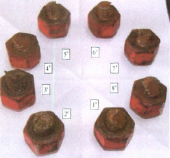
Figure 1 Figure of the rupture bolt on the bonnet side
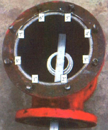
Figure 2 Figure of the body side fracture bolt
Under the optical microscope, the threads near the eight bolt fractures were observed, and it was found that the roots of the 4#, 5#, 6#, and 7# bolts had cracks, and the roots of the 1#, 2#, 3#, and 8# bolts had no cracks.
The outer diameter of 8 broken bolts and 4 polished bolts of the same batch were measured. It was found that all the broken bolts had necking deformation, and the necking deformation of 1#, 2#, 3# and 8# bolts was better. The large, 4#, 5#, 6#, and 7# bolts have less necking deformation, that is, the eight bolts that are broken are plastically deformed and elongated.
When the length of the end face of the bolt extended by the nut was measured, it was found that the amount of protrusion was greatly different, and the 7# bolt with the largest amount of protrusion was 4 mm larger than the smallest 2# bolt.
The eight bolt holes on the bonnet are crescent-shaped or squeezed into an elliptical shape, wherein the long axis of the ellipse points radially toward the center of the bonnet. The long axis and the short axis of the optical aperture were measured and the ellipticity was calculated. It was found that the 1#, 2#, 3#, and 8# optical apertures were larger than the 4#, 5#, 6#, and 7# optical apertures. One-to-one correspondence with the bolt number).
2 bolt micro analysis
The scanning electron microscope observation of the bolt fracture shows that the fractures of the 1#, 2#, 3#, and 8# bolts are dimple-like, and the shells near the roots of the 4#, 5#, 6#, and 7# bolts are found to have shell-like fatigue. The extended topography and fatigue morphology are shown in Figure 3. The energy spectrum analysis of the internal crack of the 6# bolt thread root showed that the main elements of the product were Fe, C and O, and the mass percentage of O element reached 27%.

Figure 3 Bolt fracture fatigue topography
3 bolt material analysis
3.1 Chemical composition
Sampling near the bolt fracture, chemical analysis using the Baird Spectrovac 2000 direct reading spectrometer and the LECOCS-444 infrared carbon sulfur analyzer showed that the bolt chemical composition meets the requirements of SA193)2007.
3.2 Mechanical properties
Three intact bolts were randomly selected from the same batch of broken bolts, and the tensile test specimens of the round bar with a diameter of 6.25 mm in the longitudinal direction were subjected to tensile test at room temperature to test the hardness of the fractured bolt cross section. The data shows that the bolt tensile and hardness test results are in compliance with the SA193) 2007 standard.
3.3 Metallographic organization
The samples containing the fracture and the root of the thread were taken for metallographic observation and analysis. The results were as follows: the structure was tempered sorbite, the grain size of the microstructure was 9.5, and the non-metallic inclusions were A1. 0, B0.5, D0. 5; 4#, 5#, 6#, 7# There is a crack at the root of the thread near the bolt break.
4 Comprehensive analysis of this case
The chemical composition, hardness and tensile test results of the bolts all meet the requirements of SA193)2007. The metallographic analysis shows that the bolt material is well organized. The macroscopic analysis shows that there are cracks in the roots of the threads near the fractures of 4#, 5#, 6# and 7# bolts. The 1#, 2#, 3#, and 8# bolts did not produce cracks; the 4#, 5#, 6#, and 7# bolt fracture flat areas showed fatigue marks, while 1#, 2#, 3#, 8# The bolt fracture is a microscopic appearance of a dimple-like fracture. Therefore, it is inferred that the fracture of the 4#, 5#, 6#, and 7# bolts is a fatigue fracture, and the fracture of the 1#, 2#, 3#, and 8# bolts is an overload fracture.
The force analysis of the bolt is not considered below considering the influence of the weight of the valve cover and the like. Assuming that each bolt is subjected to the same force, the tensile force of each bolt is due to the pressure of the pipeline gas:
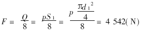
Where Q is the top drive force of the pipeline gas pressure to the valve flap, N; p is the gas pressure in the pipeline, taking p = 5.75 MPa; S1 is the area of ​​the gas acting on the valve flap, mm2; d1 is the gas acting on the valve flap The outer diameter of the area on the upper side is measured by d1 = 89.7 mm.
Refer to "Mechanical Design Basis", when the bolt is subjected to the residual locking force and the pressure of the pipeline gas, the stress on the cross section of each bolt thread is:

In the formula, F0 is the residual locking force of the bolt, F0=K0F, N; K0 is the residual locking coefficient. The mechanical design basis recommends K0 as 1.5~1.8, taking K0=1.8; S2 is the cross-sectional area of ​​the bolt thread diameter. Mm2; d2 is the bolt thread diameter, take d2=mm.
The maximum allowable stress [σ] of the bolt material is 172 MPa, so the stress load of the bolt under the normal preload force and the normal pressure of the pipeline will not exceed the allowable stress of the material.
According to the site conditions, the gas pressure is at a normal level when the bolt breaks, and the measurement results of the eight broken bolts show that the eight bolts have undergone neck plastic deformation, and the 1#, 2#, 3#, and 8# bolts are necked. The deformation is large, and the deformation of the 4#, 5#, 6#, and 7# bolts is small. Since the breakage of the 4#, 5#, 6#, and 7# bolts is a fatigue fracture, it can be inferred that these bolts are subjected to excessive tightening during the initial pre-tightening process to cause plastic deformation. Since the plastic deformation bolts are elongated, the bolts are loosened, and crescent-shaped wear occurs in the long-term friction of the bonnet bolt light holes. When the fatigue of 4#, 5#, 6#, and 7# bolts is extended to a certain extent or broken, the bolts of 1#, 2#, 3#, and 8# are all broken. Since the 1#, 2#, 3#, and 8# bolts are concentrated on the side of the force circle, when the 4#, 5#, 6#, and 7# bolts break, the overall force is unbalanced, 1#, 2#, 3# The 8# bolt plastic overload fracture is bent and deformed by the bending moment, and the bonnet light hole is laterally squeezed to cause elliptical deformation.
Excessive initial bolt stress tends to yield the bolt itself, especially in the case of small diameter bolts and low yield strength of the bolt material. When a standard wrench is used, the bolt stress generated by manual tightening is approximately
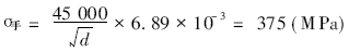
Where d is the nominal diameter of the bolt, taking the measured value d = 17.40mm.
Therefore, unless the thrust applied to the wrench is correctly judged, excessive stress is generated on the smaller bolt. The 7# bolt extension nut end face is 4mm larger than the 2# bolt with the smallest extension, indicating that the preload torque of the 8 bolts is not uniform.
Due to the fluctuation of the gas pressure in the pipeline, the bolt is subjected to the alternating stress load, and the stress concentration at the root of the thread, the excessive tightening torque will increase the stress concentration at the root of the bolt thread. After the nut was removed from the bolt, it was found that the threaded portion where the bolt and the nut were engaged was covered with rust, and it was found that the bolt fracture and the root of the thread were subjected to different degrees of oxygen corrosion. Under the action of excessive stress and corrosion, the root of the bolt thread is prone to cracks.
Based on the above analysis, it is concluded that the 4#, 5#, 6#, and 7# bolts have fatigue cracks under excessively high alternating stress and corrosion. When the fatigue cracks expand to a certain extent, the bolts are all broken due to the force overload.
The conclusion is:
1) The fracture of 1#, 2#, 3#, and 8# bolts is an overload fracture, and the fracture of 4#, 5#, 6#, and 7# bolts is fatigue fracture.
2) 4#, 5#, 6#, 7# bolt pre-tightening torque is too large, resulting in neck deformation and large stress concentration at the root of the thread. In addition, severe oxygen corrosion at the threaded part promotes the initiation and expansion of fatigue cracks at the root of the thread.
5 Solutions and effects
1) Pre-tighten the bolts with a suitable pre-tightening force. It is best to use a tightening machine that can control the torque to tighten the work.
2) Increase the bolt diameter and reduce the stress level when the bolt is working.
3) Apply grease to the threaded parts of the bolt to prevent corrosion from the external environment.
4) Regular inspections and immediate replacement of invalid or suspicious signs.
5) Through rectification, increase the nominal diameter of the bolt to 25.4mm,
Apply anti-rust grease to the bolts and tighten according to the control torque. 15 safety valves are in service for 3 years and no failure occurs. A safety valve is randomly selected to detect the bolts after disassembly. No cracks are found.
Dongguan Best Instrument Technology Co., Ltd , https://www.best-tester.com